
Model Number: YE2
Type: Asynchronous Motor
Frequency: 50HZ 60HZ
Phase: Three-phase
Protect Feature: Drip-proof
AC Voltage: 208-230 / 240 V
Efficiency: Ie 3
Product Name: YE2 series high efficiency 3 phase induction motor
Housing: Cast /Aluminium
Color: Customer Request
Poles: 2P/4P/6P/8P/10P
Power: 0.75KW-375KW
Warranty: 1-2 Years
Power Mode: Alternating current (AC)
Function Type: Driving Motor
Working Principle: Asynchronous Motor
Mounting: B3/B5/B14/B34/B35
Certification: CCC, ce
YE2 SERIES HIGH EFFICIENCY THREE-PHASE INDUCTION MOTORYE2 Series High Efficiency Three-Phase Induction Motor The three-phase asynchronous motor of the YE2 series is in line with the third efficiency standard in the provisions of GB186~8-2012 “the energy efficiency limit and the energy efficiency rating of small and medium-sized three-phase asynchronous motors”. And the improvement of the efficiency in its design is in line with the state’s requirements on the energy saving and consumption reducing of the manufacturing sector.
| YE2 SERIES HIGH EFFICIENCY THREE-PHASE INDUCTION MOTOR | |
| Motor Model | YE2 |
| Power Mode | Alternating current (AC) |
| Power Supply Phase | Three-phase motor |
| Function Type | Driving Motor |
| Working Principle | Asynchronous Motor |
●The standard motor is 380V/50HZ. A 50HZ motor with arbitrary voltage in the range of 200-600V can be designed. Under the condition that the power supply voltage deviates from the rated voltage ±5%, it can still operate well.●From product design to product delivery, follow the ISO 9001 quality certification system and strictly follow the quality procedures.
YE2 SERIES HIGH EFFICIENCY THREE-PHASE INDUCTION MOTOR MOUNTING DIMENSIONS THE COPPER COILSThe coil adopts the new national standard copper wire to ensure the high efficiency, stability and safe operation of the motor.
SEIKO BEARINGEnsure Motor Service life, high strength carbon steel quality, with good dust-proof effect.
HIGH PRECISION ROTORNew national standard rotor, multi-precision processing, through rigorous dynamic and static balance test, to ensure smooth operation and low noise.
Our Company ZheJiang CZPT GEAR TECHNOLOGY CO., LTDOur company is located in the city of HangZhou, ZheJiang Province of China. We handle the products of power transmission, our lines mainly cover series products in speed reducers, gearboxes , associated electricial motors and other power transmission accessories. Based on the versatile functions, our products can be utilized in many fields: machines of waste water treatment, dredgers, chemical industry, cranes, metal working mills, conveyors, paper industry, cement industry, cableways and so on.With the excellent quality and reasonable price , our products enjoy a good reputation from customers and the peers all over the world. Furthermore, the R&D investment are annually increasing for the purpose of better meeting the new demands of our customers and adapting the new tendency of the industry.Depending on the principles of honestly operating and mutual benefit, We sincerely look forward to cooperating with you.
Application area YE2 series motors with the mounting dimension in accordance with standard IEC60034,it has good features like optimum structure, attractive appearance, low noise, high efficiency, high protection class as well as high insulation class. YE2 series motors can be widely used in various kinds of general use machineries like fans, pumps, machine tools, compressors, transportation and son on, and can also be used in the hazardous areas with oil and chemical, steel plants, mining industry etc.
Packing&Transportion PACKING AND TRANSPORTION●Packaging: In order to ensure the integrity of product appearance, we will choose cartons, wooden pallets and wooden pallets according to customer needs.●Delivery time: Each reducer is manufactured and tested in accordance with strict and fixed procedures to ensure that the quality is correct before leaving the factory and delivery on time.●Transportation mode: We will choose the most suitable mode of transportation for our customers according to the weight and size of the goods. We can also choose the mode of transportation according to the needs of our customers.●Receiving and after-sales service: After receiving the goods, please check whether they are in good condition. We will provide customers with perfect after-sales service.
FAQ Q1: Are you a trading company or a manufacturer ?A: We are a manufacturer in ZheJiang Province, China. Our company owns the ability of manufacturing, processing, designing and R&D. We welcome your visit.Q2: How we select models and specifications?A: According to the specific details of the demands from the part of enquiry, we will recommend the products’ models upon synthesizing the factors of field of products usage, power, torque arm and ratio…Q3: How is your price? Can you offer any discount?A: Our prices are always competitive. If the customer can place a large order, we surely will allow discount.Q4: How long should I wait for the feedback after I send the enquiry?A4: We will reply as soon as possible, 12 hours at most.Q5: What is your product warranty period?A: We have the certifications of ISO9001,CE, SGS.Q6: What industries are your gearboxes being used?A: Our gearboxes are widely applied to metallurgical equipment, mining equipment, automation equipment, food machinery, packaging equipment, tobacco equipment and so on.
Online Service NMRV SERIES
CYCLOID SERIES JZQ ZSY ZLY ZD DCY SERIES
The Benefits of Using a Gear Motor
A gear motor works on the principle of conservation of angular momentum. As the smaller gear covers more RPM and the larger gear produces more torque, the ratio between the two is greater than one. Similarly, a multiple gear motor follows the principle of energy conservation, with the direction of rotation always opposite to the one that is adjacent to it. It’s easy to understand the concept behind gear motors and the various types available. Read on to learn about the different types of gears and their applications.
Electric motor
The choice of an electric motor for gear motor is largely dependent on the application. There are various motor and gearhead combinations available, and some are more efficient than others. However, it is critical to understand the application requirements and select a motor that meets these needs. In this article, we’ll examine some of the benefits of using a gear motor. The pros and cons of each type are briefly discussed. You can buy new gear motors at competitive prices, but they aren’t the most reliable or durable option for your application.
To determine which motor is best for your application, you’ll need to consider the load and speed requirements. A gear motor’s efficiency (e) can be calculated by taking the input and output values and calculating their relation. On the graph below, the input (T) and output (P) values are represented as dashed lines. The input (I) value is represented as the torque applied to the motor shaft. The output (P) is the amount of mechanical energy converted. A DC gear motor is 70% efficient at 3.75 lb-in / 2,100 rpm.
In addition to the worm gear motor, you can also choose a compact DC worm gear motor with a variable gear ratio from 7.5 to 80. It has a range of options and can be custom-made for your specific application. The 3-phase AC gear motor, on the other hand, works at a rated power of one hp and torque of 1.143.2 kg-m. The output voltage is typically 220V.
Another important factor is the output shaft orientation. There are two main orientations for gearmotors: in-line and offset. In-line output shafts are most ideal for applications with high torque and short reduction ratios. If you want to avoid backlash, choose a right angle output shaft. An offset shaft can cause the output shaft to become excessively hot. If the output shaft is angled at a certain angle, it may be too large or too small.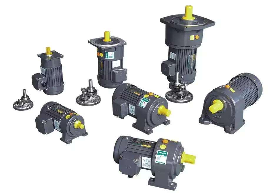
Gear reducer
A gear reducer is a special kind of speed reducing motor, usually used in large machinery, such as compressors. These reducers have no cooling fan and are not designed to handle heavy loads. Different purposes require different service factors. For instance, a machine that requires frequent fast accelerations and occasional load spikes needs a gear reducer with a high service factor. A gear reducer that’s designed for long production shifts should be larger than a machine that uses it for short periods of time.
A gear reducer can reduce the speed of a motor by a factor of two. The reduction ratio changes the rotation speed of the receiving member. This change in speed is often required to solve problems of inertia mismatch. The torque density of a gear reducer is measured in newton meters and will depend on the motor used. The first criterion is the configuration of the input and output shafts. A gear ratio of 2:1, for example, means that the output speed has been cut in half.
Bevel gear reducers are a good option if the input and output shafts are perpendicular. This type is very robust and is perfect for situations where the angle between two axes is small. However, bevel gear reducers are expensive and require constant maintenance. They are usually used in heavy-duty conveyors and farm equipment. The correct choice of gear reducer for gear motor is crucial for the efficiency and reliability of the mechanism. To get the best gear reducer for your application, talk to a qualified manufacturer today.
Choosing a gear reducer for a gear motor can be tricky. The wrong one can ruin an entire machine, so it’s important to know the specifics. You must know the torque and speed requirements and choose a motor with the appropriate ratio. A gear reducer should also be compatible with the motor it’s intended for. In some cases, a smaller motor with a gear reducer will work better than a larger one.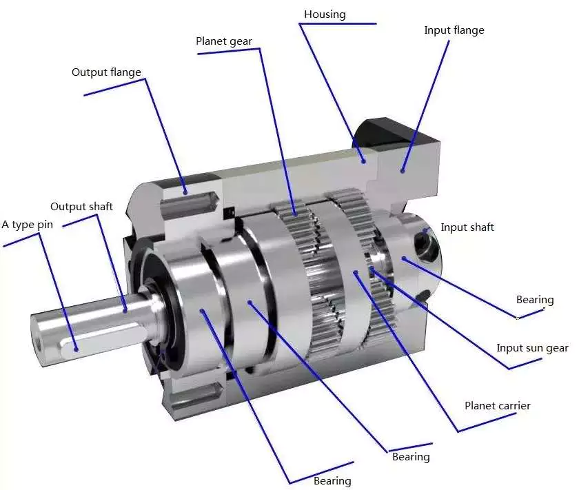
Motor shaft
Proper alignment of the motor shaft can greatly improve the performance and life span of rotating devices. The proper alignment of motors and driven instruments enhances the transfer of energy from the motor to the instrument. Incorrect alignment leads to additional noise and vibration. It may also lead to premature failure of couplings and bearings. Misalignment also results in increased shaft and coupling temperatures. Hence, proper alignment is critical to improve the efficiency of the driven instrument.
When choosing the correct type of gear train for your motor, you need to consider its energy efficiency and the torque it can handle. A helical geared motor is more efficient for high output torque applications. Depending on the required speed and torque, you can choose between an in-line and a parallel helical geared motor. Both types of gears have their advantages and disadvantages. Spur gears are widespread. They are toothed and run parallel to the motor shaft.
A planetary gear motor can also have a linear output shaft. A stepping motor should not operate at too high current to prevent demagnetization, which will lead to step loss or torque drop. Ensure that the motor and gearbox output shafts are protected from external impacts. If the motor and gearbox are not protected against bumps, they may cause thread defects. Make sure that the motor shafts and rotors are protected from external impacts.
When choosing a metal for your gear motor’s motor shaft, you should consider the cost of hot-rolled bar stock. Its outer layers are more difficult to machine. This type of material contains residual stresses and other problems that make it difficult to machine. For these applications, you should choose a high-strength steel with hard outer layers. This type of steel is cheaper, but it also has size considerations. It’s best to test each material first to determine which one suits your needs.
In addition to reducing the speed of your device, a geared motor also minimizes the torque generated by your machine. It can be used with both AC and DC power. A high-quality gear motor is vital for stirring mechanisms and conveyor belts. However, you should choose a geared motor that uses high-grade gears and provides maximum efficiency. There are many types of planetary gear motors and gears on the market, and it’s important to choose the right one.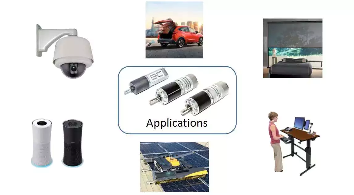
First stage gears
The first stage gears of a gear motor are the most important components of the entire device. The motor’s power transmission is 90% efficient, but there are many factors that can affect its performance. The gear ratios used should be high enough to handle the load, but not too high that they are limiting the motor’s speed. A gear motor should also have a healthy safety factor, and the lubricant must be sufficient to overcome any of these factors.
The transmission torque of the gear changes with its speed. The transmission torque at the input side of the gear decreases, transferring a small torque to the output side. The number of teeth and the pitch circle diameters can be used to calculate the torque. The first stage gears of gear motors can be categorized as spur gears, helical gears, or worm gears. These three types of gears have different torque capacities.
The first stage helical gear is the most important part of a gear motor. Its function is to transfer rotation from one gear to the other. Its output is the gearhead. The second stage gears are connected by a carrier. They work in tandem with the first stage gear to provide the output of the gearhead. Moreover, the first stage carrier rotates in the same direction as the input pinion.
Another important component is the output torque of the gearmotor. When choosing a gearmotor, consider the starting torque, running torque, output speed, overhung and shock loads, duty cycles, and more. It is crucial to choose a gearmotor with the right ratio for the application. By choosing the proper gearmotor, you will get maximum performance with minimal operating costs and increase plant productivity. For more information on first stage gears, check out our blog.
The first stage of a gear motor is composed of a set of fixed and rotating sprockets. The first stage of these gears acts as a drive gear. Its rotational mass is a limiting factor for torque. The second stage consists of a rotating shaft. This shaft rotates in the direction of the torque axis. It is also the limiting force for the motor’s torque.


editor by czh