
Product Description
Reduced Spur Geared Electric DC Gear Motor
• Manufacturer Part Number: D12 – D48
• Gearbox Type: Spur Gearbox
• Gear Ratio:1:10~1:2700
• DC Gearhead Motor Voltage: 6V, 12V, 24V, 48V
• DC Gear Reducer Size: 12 – 48mm
• Application: Safe Box Motor, Instrument Motor, Vending machine motor, Coffee maker
Features:
I. CH MOTION supply a complete range of DC gear motor. Our micro DC geared motor uses standard DC motor. Diameter of gearbox is from 12 to 37mm, and pear sharp diameter is 48mm. Voltage is from 1.5V to 24V; Power is under 10W; Speed is from 1 to several tens rpm, and Torque is under 30kg. Cm.
Structure and Characteristic of DC motor
DC motor we use has good electric and mechanical performance.
Because of volume and metal brush commutator limit, the speed of DC motor is between 3000 to 12000 rpm normally. Faster speed will decrease motor life.
Low noise DC motor with ring varistor inside is adopted, which can decrease electromagnetic disturbance to environment.
DC motor life is depending on mechanical and chemical wear of metal brush and commutator. It can continuously run over 300 to 500 hours within rated load and speed.
Structure and Characteristic of DC Gear Motor
The load torque of DC geared motor has direct relationship with speed and current. When the load increases, the speed linearly decreases and the current linearly increases. So the geared motor has better working near maximum efficiency, then it can obtain ideal running performance, working life and stable characteristic.
In general, the working environment of DC geared motor is the same as DC motor. If there are any special requirement, such as environment temperature, overload, and current limit, please illuminate in advance.
Working life of gearbox usually longer than DC motor, it can reach 1000 to 3000 hours.
Entire reduction ratio of gearbox is between 1: 10 and 1: 500. It can reach 1: 1000 with special design. However, the gearbox with bigger reduction ratio is not allowed “counter rotation”, which means the output shaft of gearbox cannot be the driving shaft and counter rotated forcedly.
The gearbox is combined with multi-pair of gears. Every pair includes CHINAMFG and pinion which is joggled 1 another. The first pinion is mounted on the motor shaft of DC motor. The bearing of gearbox output shaft is usually oil bearing made of brass or iron.
Drawing of 20mm Reduction Gearbox DC Motor
Drawing of 25mm DC Reduced Gearbox Motor
Drawing of 36mm DC Reduced Motor
Drawing of 42mm Reduction box DC Motor
Drawing of 48mm DC Motor with Gear Box
| Electrical Specification | ||||||||||
| SERIES | Figure Size | VOLTAGE V |
NO LOAD | AT MAXIMUM EFFICIENCY | STALL | |||||
| SPEED rpm |
CURRENT M A |
SPEED rpm |
TORQUE Kg . cm |
CURRENT m A |
OUTPUT m W |
TORQUE Kg . cm |
CURRENT m A |
|||
| D12 | 12mm | 2.4~6 | 17~210 | 30~120 | 12~160 | 0.16~1.5 | 150~700 | 60~640 | 0.9~4 | 240~1150 |
| D16 | 16mm | 2.4~12 | 24~400 | 40~90 | 11~330 | 0.2~2.5 | 120~440 | 90~680 | 0.8~4.5 | 400~1000 |
| D20 | 20mm | 2.4~18 | 15~620 | 30~180 | 12~500 | 0.1~4 | 60~670 | 70~1800 | 0.4~12 | 130~3500 |
| D25 | 25mm | 3~24 | 6~650 | 30~150 | 4~535 | 0.07~14 | 70~5000 | 70~4000 | 0.25~35 | 250~3000 |
| D36 | 36mm | 0~3 | 1.4~1.7 | 40~50 | 1.2~1.5 | 3.0~6.0 | 50~85 | 40~75 | 30~60 | |
| D42 | 42mm | 0~12 | 23~52 | 140~310 | 21~46 | 5.0~18 | 250~1300 | 1000~8500 | 0~30 | |
| D48 | 48mm | 6.0~24 | 2.3~60 | 40~120 | 2.0~45 | 2.0~30 | 90~600 | 530~2800 | 7~50 | 350~2500 |
| Note: We accept the customized design if the customers give us the details, thanks! | ||||||||||
Factory Ability
As a major manufacturer of high-performance DC Gear motor, DC Planetary Geared motor, Planetary gear motor, Planetary Gearbox, Gear Wheel, Spur Gearbox. I.CHMOTION is a high-tech enterprise which professionally specialized in R&D and manufacture high precise gear box reducers. We provide total solution to customers including transmission gear box design, gear parts and molding design and manufacturer, parts mass production and assembly.
Advantages
1. Many years experience in manufacturing and designing DC motor gearbox;
2. Convenient & Friendly Customer Service;
3. Low Prices Direct From Factory Suppliers;
4. High Product Performance: Low noise, High efficiency, Long lifespan;
5. Small Orders Accepted;
Package
-crate, carton or pallet;
-Shipping method: air shipping, sea shipping or express;
-Delivery time: 20-50 working days.
We can also supply similar products
DC Geared Motor with Planetary Gearbox
|
|
||
FAQ
Q: Can you make the Gearbox or Planetary Gearbox with custom specifications?
A: YES. We have strong R&D capability, also a great term of engineers, each of them have many work years experience.
Q: Do you provide the samples of DC Geared Motor?
A: YES. Our company can provide the samples to you, and the delivery time is about 5-15days according to the specification of gearbox you need.
Q: What voltage can you supply?
A: 6V, 12V, 24V or we can customized voltage.
Q: Do you have the item in stock?
A: I am sorry we do not have the item in stock, All products are made with orders.
Q: Do you provide technology support?
A: YES. Our company have strong R&D capability, we can provide technology support if you need.
Q: How to select a suitable DC Gear Motor?
A: If you have Gear motor pictures or drawings to show us, or you have detailed specs like voltage, speed, torque, motor size, working mode of the motor, life time and noise level etc, please do not hesitate to let us know, then we can recommend suitable Geared Motor per your request accordingly.
Q: Do you have customized service for your standard Planetary Gearbox Motors?
A: Yes, we can customize per your request for the voltage, speed, torque and shaft size/shape. If you need additional wires/cables soldered on the terminal or need to add connectors, or capacitors or EMC, we can make it too.
Q: Can I have samples of Planetary Gearbox for testing first?
A: Yes, definitely you can. After confirmed the needed motor specs, we will quote and provide a proforma invoice for samples, once we get the payment, we will get a PASS from our account department to proceed samples accordingly.
Q: What is application of this 12mm Geared motor?
A: Electronic Lock Motor, Optic Equipment Motor, Micro Mechanism Motor
Q: What does the share bike motor mean?
A: It means this motor is going to be used for shared bicycle, like Ofo, Mobike in China.
Q: What is the 20mm DC Geared Motor going to used for?
A: The 20mm Geared Motor is 1 kind of small size DC Geared Motors, it can be used as Storage Box Motor, Ad Equipment Motor, Audio Equipment Motor, Electronic Game Machine Motor, please choose motor depends on application size.
| Application: | Universal, Industrial, Household Appliances, Power Tools, Vending Machine, Coffee Maker |
|---|---|
| Operating Speed: | Low Speed |
| Excitation Mode: | DC Gear Motor |
| Samples: |
US$ 5/Piece
1 Piece(Min.Order) | Order Sample |
|---|
| Customization: |
Available
|
|
|---|
.shipping-cost-tm .tm-status-off{background: none;padding:0;color: #1470cc}
|
Shipping Cost:
Estimated freight per unit. |
about shipping cost and estimated delivery time. |
|---|
| Payment Method: |
|
|---|---|
|
Initial Payment Full Payment |
| Currency: | US$ |
|---|
| Return&refunds: | You can apply for a refund up to 30 days after receipt of the products. |
|---|
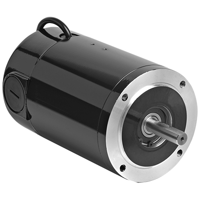
How does the speed control of a DC motor work, and what methods are commonly employed?
The speed control of a DC (Direct Current) motor is essential for achieving precise control over its rotational speed. Various methods can be employed to regulate the speed of a DC motor, depending on the specific application requirements. Here’s a detailed explanation of how speed control of a DC motor works and the commonly employed methods:
1. Voltage Control:
One of the simplest methods to control the speed of a DC motor is by varying the applied voltage. By adjusting the voltage supplied to the motor, the electromotive force (EMF) induced in the armature windings can be controlled. According to the principle of electromagnetic induction, the speed of the motor is inversely proportional to the applied voltage. Therefore, reducing the voltage decreases the speed, while increasing the voltage increases the speed. This method is commonly used in applications where a simple and inexpensive speed control mechanism is required.
2. Armature Resistance Control:
Another method to control the speed of a DC motor is by varying the armature resistance. By inserting an external resistance in series with the armature windings, the total resistance in the circuit increases. This increase in resistance reduces the armature current, thereby reducing the motor’s speed. Conversely, reducing the resistance increases the armature current and the motor’s speed. However, this method results in significant power loss and reduced motor efficiency due to the dissipation of excess energy as heat in the external resistance.
3. Field Flux Control:
Speed control can also be achieved by controlling the magnetic field strength of the motor’s stator. By altering the field flux, the interaction between the armature current and the magnetic field changes, affecting the motor’s speed. This method can be accomplished by adjusting the field current through the field windings using a field rheostat or by employing a separate power supply for the field windings. By increasing or decreasing the field flux, the speed of the motor can be adjusted accordingly. This method offers good speed regulation and efficiency but requires additional control circuitry.
4. Pulse Width Modulation (PWM):
Pulse Width Modulation is a widely used technique for speed control in DC motors. It involves rapidly switching the applied voltage on and off at a high frequency. The duty cycle, which represents the percentage of time the voltage is on, is varied to control the effective voltage applied to the motor. By adjusting the duty cycle, the average voltage across the motor is modified, thereby controlling its speed. PWM provides precise speed control, high efficiency, and low power dissipation. It is commonly employed in applications such as robotics, industrial automation, and electric vehicles.
5. Closed-Loop Control:
In closed-loop control systems, feedback from the motor’s speed or other relevant parameters is used to regulate the speed. Sensors such as encoders or tachometers measure the motor’s actual speed, which is compared to the desired speed. The difference, known as the error signal, is fed into a control algorithm that adjusts the motor’s input voltage or other control parameters to minimize the error and maintain the desired speed. Closed-loop control provides excellent speed regulation and accuracy, making it suitable for applications that require precise speed control, such as robotics and CNC machines.
These methods of speed control provide flexibility and adaptability to various applications, allowing DC motors to be effectively utilized in a wide range of industries and systems.
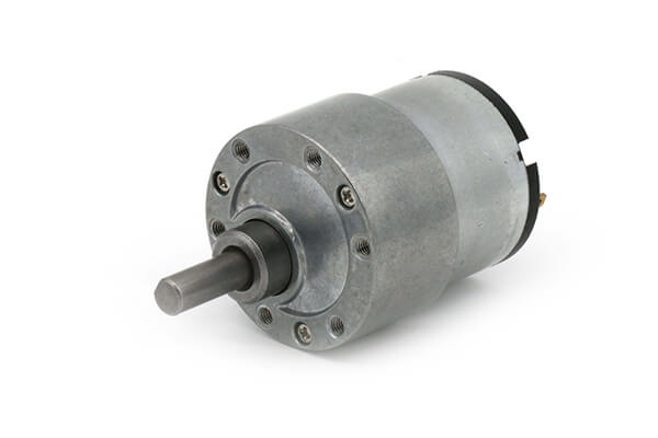
Can you explain the concept of armature winding in a DC motor?
In a DC (Direct Current) motor, the armature winding is a crucial component that plays a significant role in the motor’s operation. It is responsible for producing the magnetic field that interacts with the stator’s magnetic field, resulting in the generation of torque and the rotation of the motor. Here’s a detailed explanation of the concept of armature winding in a DC motor:
The armature winding is a coil or set of coils made of insulated wire that is wound around the armature core, which is typically a laminated iron core. The armature winding is located on the rotor of the motor and is connected to the commutator. It carries the armature current, which is the current that flows through the winding to create the magnetic field. The armature winding is usually made of copper wire due to its excellent electrical conductivity.
When a current passes through the armature winding, it generates a magnetic field around the winding according to Ampere’s circuital law. The direction of the magnetic field is determined by the right-hand rule, where the thumb represents the direction of the current flow, and the curled fingers indicate the direction of the magnetic field.
The interaction between the magnetic field produced by the armature winding and the magnetic field produced by the stator’s permanent magnets or electromagnets creates a mechanical force, known as torque. This torque causes the rotor to rotate, converting electrical energy into mechanical motion.
The armature winding is designed in such a way that it produces a multipole magnetic field. The number of poles in the winding corresponds to the number of poles in the stator’s magnetic field. This ensures that the magnetic fields of the armature and stator are properly aligned for efficient torque generation.
The armature winding is connected to the commutator, which is a cylindrical ring with multiple segments that are insulated from each other. As the rotor spins, the brushes make physical contact with different segments of the commutator, effectively reversing the direction of the current in the armature winding. This reversal of current flow ensures that the torque generated in the armature winding is always in the same direction, enabling continuous rotation of the rotor.
The design and configuration of the armature winding, including the number of turns, wire gauge, and connection scheme, can influence the motor’s performance characteristics, such as torque, speed, and efficiency. Optimal winding design is crucial for achieving the desired motor performance in various applications.
In summary, the armature winding in a DC motor is responsible for producing the magnetic field that interacts with the stator’s magnetic field, resulting in the generation of torque and the rotation of the motor. It is a critical component that facilitates the conversion of electrical energy into mechanical motion.
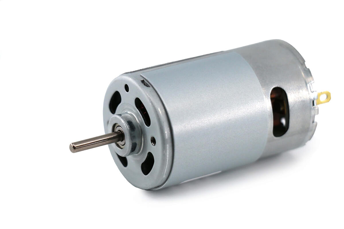
Are there safety considerations or maintenance practices associated with DC motors?
Yes, there are safety considerations and maintenance practices associated with DC (Direct Current) motors. DC motors, like any other electrical equipment, require proper handling, maintenance, and adherence to safety guidelines to ensure safe operation and longevity. Here’s a detailed explanation of the safety considerations and maintenance practices associated with DC motors:
Safety Considerations:
Electrical Hazards: DC motors operate with high voltages and currents, posing electrical hazards. It is essential to follow proper electrical safety practices, such as wearing appropriate personal protective equipment (PPE) and ensuring that electrical connections are secure and insulated. Proper grounding and isolation techniques should be employed to prevent electrical shocks and accidents.
Lockout/Tagout: DC motors, especially in industrial settings, may require maintenance or repair work. It is crucial to implement lockout/tagout procedures to isolate the motor from its power source before performing any maintenance or servicing activities. This ensures that the motor cannot be accidentally energized during work, preventing potential injuries or accidents.
Overheating and Ventilation: DC motors can generate heat during operation. Adequate ventilation and cooling measures should be implemented to prevent overheating, as excessive heat can lead to motor damage or fire hazards. Proper airflow and ventilation around the motor should be maintained, and any obstructions or debris should be cleared.
Mechanical Hazards: DC motors often have rotating parts and shafts. Safety guards or enclosures should be installed to prevent accidental contact with moving components, mitigating the risk of injuries. Operators and maintenance personnel should be trained to handle motors safely and avoid placing their hands or clothing near rotating parts while the motor is running.
Maintenance Practices:
Cleaning and Inspection: Regular cleaning and inspection of DC motors are essential for their proper functioning. Accumulated dirt, dust, or debris should be removed from the motor’s exterior and internal components. Visual inspections should be carried out to check for any signs of wear, damage, loose connections, or overheating. Bearings, if applicable, should be inspected and lubricated as per the manufacturer’s recommendations.
Brush Maintenance: DC motors that use brushes for commutation require regular inspection and maintenance of the brushes. The brushes should be checked for wear, proper alignment, and smooth operation. Worn-out brushes should be replaced to ensure efficient motor performance. Brush holders and springs should also be inspected and cleaned as necessary.
Electrical Connections: The electrical connections of DC motors should be periodically checked to ensure they are tight, secure, and free from corrosion. Loose or damaged connections can lead to voltage drops, overheating, and poor motor performance. Any issues with the connections should be addressed promptly to maintain safe and reliable operation.
Insulation Testing: Insulation resistance testing should be performed periodically to assess the condition of the motor’s insulation system. This helps identify any insulation breakdown or degradation, which can lead to electrical faults or motor failures. Insulation resistance testing should be conducted following appropriate safety procedures and using suitable testing equipment.
Alignment and Balance: Proper alignment and balance of DC motors are crucial for their smooth operation and longevity. Misalignment or imbalance can result in increased vibrations, excessive wear on bearings, and reduced motor efficiency. Regular checks and adjustments should be made to ensure the motor is correctly aligned and balanced as per the manufacturer’s specifications.
Manufacturer’s Recommendations: It is important to refer to the manufacturer’s guidelines and recommendations for specific maintenance practices and intervals. Each DC motor model may have unique requirements, and following the manufacturer’s instructions ensures that maintenance is carried out correctly and in accordance with the motor’s design and specifications.
By adhering to safety considerations and implementing proper maintenance practices, DC motors can operate safely, reliably, and efficiently throughout their service life.


editor by CX 2023-10-23