
|
Output Kw |
Type |
Amps A |
Speed r / min |
Eff. % |
P.F |
RTN.m | LRT RLT | BDT RLT | LRA RLA |
Noise LW dB(A) |
Weight kg |
|
380V 50Hz 2-Pole |
|||||||||||
|
0.18 |
Y2-631-2 |
0.5 |
2800 |
65.0 |
0.80 |
0.61 |
2.2 |
2.2 |
5.5 |
61 |
14 |
|
0.25 |
Y2-632-2 |
0.7 |
2800 |
68.0 |
0.81 |
0.96 |
2.2 |
2.2 |
5.5 |
61 |
14.5 |
|
0.37 |
Y2-711-2 |
1.0 |
2800 |
70.0 |
0.81 |
1.26 |
2.2 |
2.2 |
6.1 |
64 |
15 |
|
0.55 |
Y2-712-2 |
1.4 |
2800 |
73.0 |
0.82 |
1.88 |
2.2 |
2.2 |
6.1 |
64 |
15.5 |
|
0.75 |
Y2-801-2 |
1.8 |
2825 |
75.0 |
0.83 |
2.54 |
2.2 |
2.3 |
6.1 |
67 |
16.5 |
|
1.1 |
Y2-802-2 |
2.6 |
2825 |
77.0 |
0.84 |
3.72 |
2.2 |
2.3 |
7.0 |
67 |
17.5 |
|
1.5 |
Y2-90S-2 |
3.4 |
2840 |
79.0 |
0.84 |
5.04 |
2.2 |
2.3 |
7.0 |
72 |
21 |
|
2.2 |
Y2-90L-2 |
4.9 |
2840 |
81.0 |
0.85 |
7.40 |
2.2 |
2.3 |
7.0 |
72 |
25 |
|
3 |
Y2-100L-2 |
6.3 |
2880 |
83.0 |
0.87 |
9.95 |
2.2 |
2.3 |
7.5 |
76 |
33 |
|
4 |
Y2-112M-2 |
8.1 |
2890 |
85.0 |
0.88 |
13.22 |
2.2 |
2.3 |
7.5 |
77 |
41 |
|
5.5 |
Y2-132S1-2 |
11.0 |
2900 |
86.0 |
0.88 |
18.11 |
2.2 |
2.3 |
7.5 |
80 |
63 |
|
7.5 |
Y2-132S2-2 |
14.9 |
2900 |
87.0 |
0.88 |
24.70 |
2.2 |
2.3 |
7.5 |
80 |
70 |
|
11 |
Y2-160M1-2 |
21. |
2930 |
88.4 |
0.89 |
35.85 |
2.2 |
2.3 |
7.5 |
86 |
110 |
|
15 |
Y2-160M2-2 |
28.8 |
2930 |
89.4 |
0.89 |
48.89 |
2.2 |
2.3 |
7.5 |
86 |
120 |
|
18.5 |
Y2-160L-2 |
34.7 |
2930 |
90.0 |
0.90 |
60.30 |
2.2 |
2.3 |
7.5 |
86 |
135 |
|
22 |
Y2-180M-2 |
41.0 |
2940 |
90.5 |
0.90 |
71.46 |
2.0 |
2.3 |
7.5 |
89 |
165 |
|
30 |
Y2-200L1-2 |
55.5 |
2950 |
91.4 |
0.90 |
97.12 |
2.0 |
2.3 |
7.5 |
92 |
218 |
|
37 |
Y2-200L2-2 |
67.9 |
2950 |
92.0 |
0.90 |
119.78 |
2.0 |
2.3 |
7.5 |
92 |
230 |
|
45 |
Y2-225M-2 |
82.3 |
2970 |
92.5 |
0.90 |
114.70 |
2.0 |
2.3 |
7.5 |
92 |
280 |
|
55 |
Y2-250M-2 |
100.4 |
2970 |
93.0 |
0.90 |
176.85 |
2.0 |
2.3 |
7.5 |
93 |
365 |
|
75 |
Y2-280S-2 |
134.4 |
2970 |
93.6 |
0.91 |
241.16 |
2.0 |
2.3 |
7.5 |
94 |
495 |
| 90 | Y2-280M-2 | 160.2 | 2970 | 93.9 | 0.91 | 289.39 | 2.0 | 2.3 | 7.5 | 94 | 565 |
| 110 | Y2-315S-2 | 195.4 | 2980 | 94.0 | 0.91 | 352.51 | 1.8 | 2.2 | 7.1 | 96 | 890 |
| 132 | Y2-315M-2 | 233.2 | 2980 | 94.5 | 0.91 | 423.02 | 1.8 | 2.2 | 7.1 | 96 | 980 |
| 160 | Y2-315L1-2 | 279.3 | 2980 | 94.6 | 0.92 | 512.75 | 1.8 | 2.2 | 7.1 | 99 | 1055 |
| 200 | Y2-315L2-2 | 348.4 | 2980 | 94.8 | 0.92 | 640.94 | 1.8 | 2.2 | 7.1 | 99 | 1110 |
|
380V 50Hz 4-Pole |
|||||||||||
| 0.12 |
Y2-631-4 |
0.4 | 1400 | 57.0 | 0.72 | 0.82 | 2.1 | 2.2 | 4.4 | 52 | 13 |
| 0.18 |
Y2-632-4 |
0.6 | 1400 | 60.0 | 0.73 | 1.23 | 2.1 | 2.2 | 4.4 | 52 | 13.5 |
| 0.25 |
Y2-711-4 |
0.8 | 1400 | 65.0 | 0.74 | 1.71 | 2.1 | 2.2 | 5.2 | 55 | 14 |
| 0.37 |
Y2-712-4 |
1.1 | 1400 | 67.0 | 0.75 | 2.54 | 2.1 | 2.2 | 5.2 | 55 | 14.5 |
| 0.55 |
Y2-801-4 |
1.6 | 1390 | 71.0 | 0.75 | 3.78 | 2.4 | 2.3 | 5.2 | 58 | 15 |
| 0.75 |
Y2-802-4 |
2.0 | 1390 | 73.0 | 0.77 | 5.15 | 2.4 | 2.3 | 6.0 | 58 | 16 |
| 1.1 |
Y2-90S-4 |
2.9 | 1400 | 76.2 | 0.77 | 7.50 | 2.3 | 2.3 | 6.0 | 61 | 23 |
| 1.5 |
Y2-90L-4 |
3.7 | 1400 | 78.5 | 0.79 | 10.23 | 2.3 | 2.3 | 6.0 | 61 | 25 |
| 2.2 |
Y2-100L1-4 |
5.2 | 1420 | 81.0 | 0.81 | 14.80 | 2.3 | 2.3 | 7.0 | 64 | 33 |
| 3 | Y2-100L2-4 | 6.8 | 1420 | 82.6 | 0.82 | 20.18 | 2.3 | 2.3 | 7.0 | 64 | 35 |
| 4 | Y2-112M-4 | 8.8 | 1440 | 84.2 | 0.82 | 26.53 | 2.3 | 2.3 | 7.0 | 65 | 41 |
| 5.5 | Y2-132S-4 | 11.8 | 1440 | 85.7 | 0.83 | 36.48 | 2.3 | 2.3 | 7.0 | 71 | 65 |
| 7.5 | Y2-132M-4 | 15.6 | 1440 | 87.0 | 0.84 | 49.74 | 2.3 | 2.3 | 7.0 | 71 | 76 |
| 11 | Y2-160M-4 | 22.3 | 1460 | 88.4 | 0.85 | 71.59 | 2.2 | 2.3 | 7.0 | 75 | 118 |
| 15 | Y2-160L-4 | 30.1 | 1460 | 89.4 | 0.85 | 98.12 | 2.2 | 2.3 | 7.5 | 75 | 132 |
| 18.5 | Y2-180M-4 | 36.5 | 1470 | 90.5 | 0.85 | 120.19 | 2.2 | 2.3 | 7.5 | 76 | 164 |
| 22 | Y2-180L-4 | 43.2 | 1470 | 91.0 | 0.85 | 142.93 | 2.2 | 2.3 | 7.5 | 76 | 182 |
| 30 | Y2-200L-4 | 57.6 | 1480 | 92.0 | 0.86 | 160.96 | 2.2 | 2.3 | 7.2 | 79 | 245 |
| 37 | Y2-225S-4 | 69.9 | 1480 | 92.5 | 0.87 | 198.51 | 2.2 | 2.3 | 7.2 | 81 | 258 |
| 45 |
Y2-225M-4 |
84.7 | 1480 | 92.8 | 0.87 | 290.37 | 2.2 | 2.3 | 7.2 | 81 | 290 |
| 55 |
Y2-250M-4 |
103.3 | 1480 | 93.0 | 0.87 | 354.90 | 2.2 | 2.3 | 7.2 | 83 | 388 |
| 75 |
Y2-280S-4 |
139.3 | 1480 | 93.8 | 0.87 | 483.95 | 2.2 | 2.3 | 7.2 | 86 | 510 |
| 90 | Y2-280M-4 | 166.9 | 1485 | 94.2 | 0.87 | 578.79 | 2.2 | 2.3 | 7.2 | 86 | 606 |
| 110 | Y2-315S-4 | 201.0 | 1485 | 94.5 | 0.88 | 707.41 | 2.1 | 2.2 | 6.9 | 93 | 910 |
| 132 | Y2-315M-4 | 240.4 | 1485 | 94.8 | 0.88 | 848.89 | 2.1 | 2.2 | 6.9 | 93 | 1000 |
| 160 | Y2-315L1-4 | 287.8 | 1485 | 94.9 | 0.89 | 1571.96 | 2.1 | 2.2 | 6.9 | 97 | 1055 |
| 200 | Y2-315L2-4 | 359.4 | 1485 | 95.0 | 0.89 | 1286.20 | 2.1 | 2.2 | 6.9 | 97 | 1128 |
|
380V 50Hz 6-Pole |
|||||||||||
| 0.18 |
Y2-711-6 |
0.8 | 900 | 56.0 | 0.66 | 1.91 | 1.9 | 2.0 | 4.0 | 52 | 14 |
| 0.25 |
Y2-712-6 |
0.9 | 900 | 59.0 | 0.68 | 2.65 | 1.9 | 2.0 | 4.0 | 52 | 14.5 |
| 0.37 |
Y2-801-6 |
1.3 | 900 | 62.0 | 0.70 | 3.93 | 1.9 | 2.0 | 4.7 | 54 | 15 |
| 0.55 |
Y2-802-6 |
1.8 | 900 | 65.0 | 0.72 | 5.84 | 1.9 | 2.1 | 4.7 | 54 | 16 |
| 0.75 |
Y2-90S-6 |
2.3 | 910 | 69.0 | 0.72 | 7.87 | 2.0 | 2.1 | 5.5 | 57 | 19 |
| 1.1 |
Y2-90L-6 |
3.2 | 910 | 72.0 | 0.73 | 11.54 | 2.0 | 2.1 | 5.5 | 57 | 22 |
| 1.5 |
Y2-100L-6 |
3.9 | 940 | 76.0 | 0.76 | 15.24 | 2.0 | 2.1 | 5.5 | 61 | 32 |
| 2.2 |
Y2-112M-6 |
5.6 | 940 | 79.0 | 0.76 | 22.35 | 2.1 | 2.1 | 6.5 | 65 | 41 |
| 3 |
Y2-132S-6 |
7.4 | 960 | 81.0 | 0.76 | 29.84 | 2.1 | 2.1 | 6.5 | 69 | 63 |
| 4 | Y2-132M1-6 | 9.9 | 960 | 82.0 | 0.76 | 39.79 | 2.1 | 2.1 | 6.5 | 69 | 72 |
| 5.5 | Y2-132M2-6 | 12.9 | 960 | 84.0 | 0.77 | 54.71 | 2.1 | 2.1 | 6.5 | 69 | 81 |
| 7.5 | Y2-160M-6 | 16.9 | 970 | 86.0 | 0.78 | 73.84 | 2.0 | 2.1 | 6.5 | 73 | 118 |
| 11 | Y2-160L-6 | 24.2 | 970 | 87.5 | 0.79 | 108.30 | 2.0 | 2.1 | 6.5 | 73 | 145 |
| 15 | Y2-180L-6 | 31.6 | 970 | 89.0 | 0.81 | 147.68 | 2.1 | 2.1 | 7.0 | 73 | 178 |
| 18.5 | Y2-200L1-6 | 38.6 | 970 | 90.0 | 0.81 | 182.14 | 2.1 | 2.1 | 7.0 | 76 | 200 |
| 22 | Y2-200L2-6 | 44.7 | 970 | 90.0 | 0.83 | 216.60 | 2.1 | 2.1 | 7.0 | 76 | 228 |
| 30 | Y2-225M-6 | 59.3 | 980 | 91.5 | 0.84 | 292.35 | 2.0 | 2.1 | 7.0 | 76 | 265 |
| 37 | Y2-250M-6 | 71.1 | 980 | 92.0 | 0.86 | 360.56 | 2.1 | 2.1 | 7.0 | 78 | 370 |
| 45 | Y2-280S-6 | 85.9 | 980 | 92.5 | 0.86 | 438.52 | 2.1 | 2.0 | 7.0 | 80 | 490 |
| 55 | Y2-280M-6 | 104.7 | 980 | 92.8 | 0.86 | 535.97 | 2.1 | 2.0 | 7.0 | 80 | 540 |
| 75 | Y2-315S-6 | 141.7 | 980 | 93.5 | 0.86 | 730.87 | 2.0 | 2.0 | 7.0 | 85 | 900 |
| 90 | Y2-315M-6 | 169.5 | 985 | 93.8 | 0.86 | 872.59 | 2.0 | 2.0 | 7.0 | 85 | 980 |
| 110 | Y2-315L2-6 | 206.7 | 985 | 94.0 | 0.86 | 1066.50 | 2.0 | 2.0 | 6.7 | 85 | 1045 |
| 132 | YW2-315L2-6 | 244.7 | 985 | 94.2 | 0.87 | 1279.80 | 2.0 | 2.0 | 6.7 | 85 | 1100 |
| 380V 50Hz 8-Pole | |||||||||||
| 0.18 | Y2-801-8 | 0.9 | 690 | 51.0 | 0.61 | 2.49 | 1.8 | 1.9 | 3.3 | 52 | 22 |
| 0.25 | Y2-802-8 | 1.2 | 690 | 54.0 | 0.61 | 3.46 | 1.8 | 1.9 | 3.3 | 52 | 24 |
| 0.37 | Y2-90S-8 | 1.5 | 690 | 62.0 | 0.61 | 5.12 | 1.8 | 1.9 | 4.0 | 56 | 26 |
| 0.55 | Y2-90L-8 | 2.2 | 690 | 63.0 | 0.61 | 7.61 | 1.8 | 5.0 | 59 | 32 | |
| 1.5 | Y2-112M-8 | 4.4 | 700 | 75.0 | 0.68 | 20.46 | 1.8 | 2.0 | 5.0 | 61 | 40 |
| 2.2 | Y2-132S-8 | 6.0 | 710 | 78.0 | 0.71 | 29.59 | 1.8 | 2.0 | 6.0 | 64 | 64 |
| 3 | Y2-132M-8 | 7.9 | 710 | 79.0 | 0.73 | 4035 | 1.8 | 2.0 | 6.0 | 64 | 78 |
| 4 | Y2-160M1-8 | 10.3 | 720 | 81.0 | 0.73 | 53.06 | 1.9 | 2.0 | 6.0 | 68 | 105 |
| 5.5 | Y2-160M2-8 | 13.6 | 720 | 83.0 | 0.74 | 72.59 | 2.0 | 2.0 | 6.0 | 68 | 115 |
| 7.5 | Y2-160L-8 | 17.8 | 720 | 85.5 | 0.75 | 99.50 | 2.0 | 2.0 | 6.0 | 68 | 145 |
| 11 | Y2-180L-8 | 25.1 | 730 | 87.5 | 0.76 | 143.90 | 2.0 | 2.0 | 6.6 | 70 | 160 |
| 15 | YL-200L-8 | 34.1 | 730 | 88.0 | 0.76 | 196.23 | 2.0 | 2.0 | 6.6 | 73 | 228 |
| 18.5 | Y2-225S-8 | 41.1 | 730 | 90.0 | 0.76 | 242.02 | 1.9 | 2.0 | 6.6 | 73 | 242 |
| 22 | Y2-225M-8 | 47.5 | 730 | 90.5 | 0.78 | 287.81 | 1.9 | 2.0 | 6.6 | 73 | 265 |
| 30 | Y2-250M-8 | 63.4 | 730 | 91.0 | 0.79 | 392.47 | 1.9 | 2.0 | 6.6 | 75 | 368 |
| 37 | Y2-280S-8 | 77.8 | 730 | 91.5 | 0.79 | 484.04 | 1.9 | 2.0 | 6.6 | 76 | 472 |
| 45 | Y2-280M-8 | 94.1 | 740 | 92.0 | 0.79 | 580.74 | 1.8 | 2.0 | 6.6 | 76 | 538 |
| 55 | Y2-315S-8 | 111.2 | 740 | 92.8 | 0.81 | 709.80 | 1.8 | 2.0 | 6.6 | 82 | 900 |
| 75 | Y2-315M-8 | 151.3 | 740 | 93.0 | 0.81 | 967.91 | 1.8 | 2.0 | 6.6 | 82 | 1000 |
| 90 | Y2-315L1-8 | 177.8 | 740 | 93.8 | 0.82 | 1161049 | 1.8 | 2.0 | 6.6 | 82 | 1055 |
| 110 | Y2-315L2-8 | 216.8 | 740 | 94.0 | 0.82 | 1419.60 | 1.8 | 2.0 | 6.4 | 82 | 1118 |
| 380V 50Hz 10-Pole | |||||||||||
| 45 | Y2-315S-8 | 99.6 | 590 | 91.5 | 0.75 | 728.39 | 1.5 | 2.0 | 6.2 | 82 | 818 |
| 55 | Y2-315M-8 | 121.1 | 590 | 92.0 | 0.75 | 890.25 | 1.5 | 2.0 | 6.2 | 82 | 928 |
| 75 | Y2-315L1-8 | 162.1 | 590 | 92.5 | 0.76 | 1213.98 | 1.5 | 2.0 | 6.2 | 82 | 1080 |
| 90 | Y2-315L2-8 | 191.0 | 590 | 93.0 | 0.77 | 1456.78 | 1.5 | 2.0 | 6.2 | 82 | 1200 |
Y2 collection 3-period induction motor
DESCRIPTION
Y2 sequence 3-period asynchronous electric powered motor, designed with new strategies, are energy-preserving items in rigid conformity to the IEC normal.
Y2 collection motor are defined as entirely enclosed, fancooled, squirrel cage kind and have this sort of good features as novel design and style, beautiful modeling, low noising, high performance and large torque. The frames and endshields are produced of solid iron or aluminum-alloy, and all cooling CZPT of motor assume vertical or horizontal distribution. Additionally, these motor have outstanding beginning performance, compact construction and effortless serving. They are adopted with F class insulation and developed with evaluating technique for insulation method in accordance to worldwide follow. The PTC thermistors or thermal protectors can be mounted according to the special needs of consumers. The defense degree reaches IP54 or IP55 so that it significantly improves motor’s security and dependability. For that reason, these motor have reached an international superior amount of such kind of items.
Y2 series motor can be extensively utilized as driving equipments of a variety of machineries, this sort of as machine resources, blowers, pumps, compressors, transporters, agricultural and food processing.
Operation CONDITIONS㏒o
Ambient temperature: -15 – 40
Altitude: Altitude ought to be decrease than 1000meters over sea level.
Rated voltage:380V.
Rated frequency:50Hz.
Link:Star-connection for 3KW or significantly less whereas delta-connection for 4KW or a lot more.
Duty/Score:Constant(S1).
Cooling approach: ICO141.
Detailed Complex Information
Dynamic Modeling of a Planetary Motor
A planetary gear motor consists of a series of gears rotating in perfect synchrony, allowing them to deliver torque in a higher output capacity than a spur gear motor. Unlike the planetary motor, spur gear motors are simpler to build and cost less, but they are better for applications requiring lower torque output. That is because each gear carries the entire load. The following are some key differences between the 2 types of gearmotors.
planetary gear system
A planetary gear transmission is a type of gear mechanism that transfers torque from 1 source to another, usually a rotary motion. Moreover, this type of gear transmission requires dynamic modeling to investigate its durability and reliability. Previous studies included both uncoupled and coupled meshing models for the analysis of planetary gear transmission. The combined model considers both the shaft structural stiffness and the bearing support stiffness. In some applications, the flexible planetary gear may affect the dynamic response of the system.
In a planetary gear device, the axial end surface of the cylindrical portion is rotatable relative to the separating plate. This mechanism retains lubricant. It is also capable of preventing foreign particles from entering the planetary gear system. A planetary gear device is a great choice if your planetary motor’s speed is high. A high-quality planetary gear system can provide a superior performance than conventional systems.
A planetary gear system is a complex mechanism, involving 3 moving links that are connected to each other through joints. The sun gear acts as an input and the planet gears act as outputs. They rotate about their axes at a ratio determined by the number of teeth on each gear. The sun gear has 24 teeth, while the planet gears have 3-quarters that ratio. This ratio makes a planetary motor extremely efficient.
planetary gear train
To predict the free vibration response of a planetary motor gear train, it is essential to develop a mathematical model for the system. Previously, static and dynamic models were used to study the behavior of planetary motor gear trains. In this study, a dynamic model was developed to investigate the effects of key design parameters on the vibratory response. Key parameters for planetary gear transmissions include the structure stiffness and mesh stiffness, and the mass and location of the shaft and bearing supports.
The design of the planetary motor gear train consists of several stages that can run with variable input speeds. The design of the gear train enables the transmission of high torques by dividing the load across multiple planetary gears. In addition, the planetary gear train has multiple teeth which mesh simultaneously in operation. This design also allows for higher efficiency and transmittable torque. Here are some other advantages of planetary motor gear trains. All these advantages make planetary motor gear trains 1 of the most popular types of planetary motors.
The compact footprint of planetary gears allows for excellent heat dissipation. High speeds and sustained performances will require lubrication. This lubricant can also reduce noise and vibration. But if these characteristics are not desirable for your application, you can choose a different gear type. Alternatively, if you want to maintain high performance, a planetary motor gear train will be the best choice. So, what are the advantages of planetary motor gears?
planetary gear train with fixed carrier train ratio
The planetary gear train is a common type of transmission in various machines. Its main advantages are high efficiency, compactness, large transmission ratio, and power-to-weight ratio. This type of gear train is a combination of spur gears, single-helical gears, and herringbone gears. Herringbone planetary gears have lower axial force and high load carrying capacity. Herringbone planetary gears are commonly used in heavy machinery and transmissions of large vehicles.
To use a planetary gear train with a fixed carrier train ratio, the first and second planets must be in a carrier position. The first planet is rotated so that its teeth mesh with the sun’s. The second planet, however, cannot rotate. It must be in a carrier position so that it can mesh with the sun. This requires a high degree of precision, so the planetary gear train is usually made of multiple sets. A little analysis will simplify this design.
The planetary gear train is made up of 3 components. The outer ring gear is supported by a ring gear. Each gear is positioned at a specific angle relative to 1 another. This allows the gears to rotate at a fixed rate while transferring the motion. This design is also popular in bicycles and other small vehicles. If the planetary gear train has several stages, multiple ring gears may be shared. A stationary ring gear is also used in pencil sharpener mechanisms. Planet gears are extended into cylindrical cutters. The ring gear is stationary and the planet gears rotate around a sun axis. In the case of this design, the outer ring gear will have a -3/2 planet gear ratio.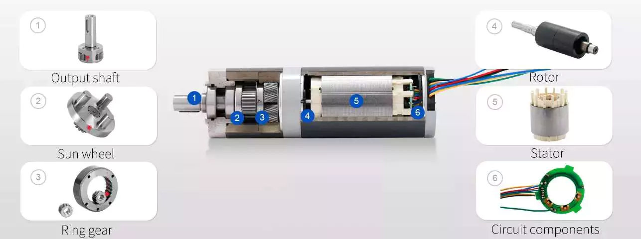
planetary gear train with 0 helix angle
The torque distribution in a planetary gear is skewed, and this will drastically reduce the load carrying capacity of a needle bearing, and therefore the life of the bearing. To better understand how this can affect a gear train, we will examine 2 studies conducted on the load distribution of a planetary gear with a 0 helix angle. The first study was done with a highly specialized program from the bearing manufacturer INA/FAG. The red line represents the load distribution along a needle roller in a 0 helix gear, while the green line corresponds to the same distribution of loads in a 15 degree helix angle gear.
Another method for determining a gear’s helix angle is to consider the ratio of the sun and planet gears. While the sun gear is normally on the input side, the planet gears are on the output side. The sun gear is stationary. The 2 gears are in engagement with a ring gear that rotates 45 degrees clockwise. Both gears are attached to pins that support the planet gears. In the figure below, you can see the tangential and axial gear mesh forces on a planetary gear train.
Another method used for calculating power loss in a planetary gear train is the use of an auto transmission. This type of gear provides balanced performance in both power efficiency and load capacity. Despite the complexities, this method provides a more accurate analysis of how the helix angle affects power loss in a planetary gear train. If you’re interested in reducing the power loss of a planetary gear train, read on!
planetary gear train with spur gears
A planetary gearset is a type of mechanical drive system that uses spur gears that move in opposite directions within a plane. Spur gears are 1 of the more basic types of gears, as they don’t require any specialty cuts or angles to work. Instead, spur gears use a complex tooth shape to determine where the teeth will make contact. This in turn, will determine the amount of power, torque, and speed they can produce.
A 2-stage planetary gear train with spur gears is also possible to run at variable input speeds. For such a setup, a mathematical model of the gear train is developed. Simulation of the dynamic behaviour highlights the non-stationary effects, and the results are in good agreement with the experimental data. As the ratio of spur gears to spur gears is not constant, it is called a dedendum.
A planetary gear train with spur gears is a type of epicyclic gear train. In this case, spur gears run between gears that contain both internal and external teeth. The circumferential motion of the spur gears is analogous to the rotation of planets in the solar system. There are 4 main components of a planetary gear train. The planet gear is positioned inside the sun gear and rotates to transfer motion to the sun gear. The planet gears are mounted on a joint carrier that is connected to the output shaft.
planetary gear train with helical gears
A planetary gear train with helical teeth is an extremely powerful transmission system that can provide high levels of power density. Helical gears are used to increase efficiency by providing a more efficient alternative to conventional worm gears. This type of transmission has the potential to improve the overall performance of a system, and its benefits extend far beyond the power density. But what makes this transmission system so appealing? What are the key factors to consider when designing this type of transmission system?
The most basic planetary train consists of the sun gear, planet gear, and ring gear elements. The number of planets varies, but the basic structure of planetary gears is similar. A simple planetary geartrain has the sun gear driving a carrier assembly. The number of planets can be as low as 2 or as high as 6. A planetary gear train has a low mass inertia and is compact and reliable.
The mesh phase properties of a planetary gear train are particularly important in designing the profiles. Various parameters such as mesh phase difference and tooth profile modifications must be studied in depth in order to fully understand the dynamic characteristics of a PGT. These factors, together with others, determine the helical gears’ performance. It is therefore essential to understand the mesh phase of a planetary gear train to design it effectively.

