
Product Description
Product Description
Feature:
A. High power range from 50W to 2KW
B. Dia: 57mm-110mm
C. Easy for speed & direction adjustment
D. Rich stock and fast shipping time in 10 working days
E. Strong stability for driver/controller
F. Lifetime above continuous 10000 hours
G. IP65 protection rank is available for us
H. Above 90% enery efficiency motor is available
I. 3D file is available if customers needed
K.High-performance and stable matching driver and controller
Kindly remind: As different customers may need different motor parameter for fitting your equipment. If below motor can’t fit your need, please kindly send inquiry to us with information for rated power or torque,rated speed, and rated voltage for our new size drawing making for you. CLICK HERE to contact me. Thanks a lot!
Δ 86mm BLDC Motor with RV40 Worm Gearbox Size Dimensions
Dimensions (Unit: mm )
Mounting screws are included with gear head.
Δ Brushless DC Motor Specification:
|
Motor Power (W) |
600 |
1000 |
1500 |
|
Motor Length(mm) |
123 |
153 |
183 |
|
Motor Rated Speed(rpm) |
2000 |
||
Δ RV63 Worm Gearbox Specification:
| Gear Ratio | 7.5 | 10 | 15 | 20 | 25 | 30 | 40 | 50 | 60 | 80 | 100 |
| Rated output speed(rpm) | 267 | 200 | 133 | 100 | 80 | 67 | 50 | 40 | 33 | 25 | 20 |
| Rated Torque(N.m) | 28.7 | 38.2 | 57.3 | 74.5 | 90.7 | 106 | 133.7 | 124 | 94 | 115 | 87 |
Other Specification form:
Δ Motor interface, Voltage, Speed can be customized.
For More Details Of Product Specifications,
Please Click here contact us for updated size drawing if you have other different parameter needed. Thanks
More Motor Flange Size
Δ More Motor Flange Size to choose, if you need other size. Welcome to contact us to custom.
BLDC Motor with Gearbox Range
Company Profile
DMKE motor was founded in China, HangZhou city,Xihu (West Lake) Dis. district, in 2009. After 12 years’ creativity and development, we became 1 of the leading high-tech companies in China in dc motor industry.
We specialize in high precision micro dc gear motors, brushless motors, brushless controllers, dc servo motors, dc servo controllers etc. And we produce brushless dc motor and controller with wide power range from 5 watt to 20 kilowatt; also dc servo motor power range from 50 watt to 10 kilowatt. They are widely used in automatic guided vehicle , robots, lifting equipment,cleaning machine, medical equipment, packing machinery, and many other industrial automatic equipments.
With a plant area of 4000 square meters, we have built our own supply chain with high quality control standard and passed ISO9001 certificate of quality system.
With more than 10 engineers for brushless dc motor and controllers’ research and development, we own strong independent design and development capability. Custom-made motors and controllers are widely accepted by us. At the same time, we have engineers who can speak fluent English. That makes we can supply intime after-sales support and guidance smoothly for our customers.
Our motors are exported worldwide, and over 80% motors are exported to Europe, the United States, Saudi Arabia, Australia, Korea etc. We are looking CHINAMFG to establishing long-term business relationship together with you for mutual business success.
FAQ
Q1: What kind motors you can provide?
A1: For now, we mainly provide permanent magnet brushless dc motor, dc gear motor, micro dc motor, planetary gear motor, dc servo motor, brush dc motors, with diameter range from 16 to 220mm,and power range from 5W to 20KW.
Q2: Is there a MOQ for your motors?
A2: No. we can accept 1 pcs for sample making for your testing,and the price for sample making will have 10% to 30% difference than bulk price based on different style.
Q3: Could you send me a price list?
A3: For all of our motors, they are customized based on different requirements like power, voltage, gear ratio, rated torque and shaft diameter etc. The price also varies according to different order qty. So it’s difficult for us to provide a price list.
If you can share your detailed specification and order qty, we’ll see what offer we can provide.
Q4: Are you motors reversible?
A4: Yes, nearly all dc and ac motor are reversible. We have technical people who can teach how to get the function by different wire connection.
Q5: Is it possible for you to develop new motors if we provide the tooling cost?
A5: Yes. Please kindly share the detailed requirements like performance, size, annual quantity, target price etc. Then we’ll make our evaluation to see if we can arrange or not.
Q6:How about your delivery time?
A6: For micro brush dc gear motor, the sample delivery time is 2-5 days, bulk delivery time is about 15-20 days, depends on the order qty.
For brushless dc motor, the sample deliver time is about 10-15 days; bulk time is 15-20 days.
Pleasecontact us for final reference.
Q7:What’s your warranty terms?
A6: One year /* January 22, 2571 19:08:37 */!function(){function s(e,r){var a,o={};try{e&&e.split(“,”).forEach(function(e,t){e&&(a=e.match(/(.*?):(.*)$/))&&1
| Application: | Universal, Industrial, Household Appliances, Power Tools |
|---|---|
| Operating Speed: | Adjust Speed |
| Excitation Mode: | Compound |
| Function: | Control, Driving |
| Casing Protection: | Protection Type |
| Number of Poles: | 8 |
| Samples: |
US$ 275.4/Piece
1 Piece(Min.Order) | |
|---|
| Customization: |
Available
|
|
|---|
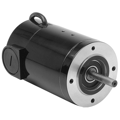
What are the main components of a DC motor, and how do they contribute to its functionality?
A DC (Direct Current) motor consists of several key components that work together to enable its functionality. Each component plays a crucial role in the operation of the motor. Here’s a detailed explanation of the main components of a DC motor and their contributions:
1. Stator:
The stator is the stationary part of the motor. It typically consists of permanent magnets or electromagnets that produce a fixed magnetic field. The stator’s magnetic field interacts with the rotor’s magnetic field to generate the required torque for motor rotation. The stator provides the foundation for the motor’s magnetic field and contributes to its overall stability and efficiency.
2. Rotor:
The rotor is the rotating part of the motor and is connected to the motor’s output shaft. It contains coils or windings that carry the armature current. The rotor’s windings interact with the stator’s magnetic field, resulting in the generation of a mechanical force that causes the rotor to rotate. The rotor’s movement is responsible for converting electrical energy into mechanical motion, enabling the motor to perform its intended function.
3. Armature:
The armature is the core of the rotor that holds the armature windings. The armature windings are typically made of copper wire and are evenly spaced around the armature. When a current passes through the armature windings, a magnetic field is created around them. This magnetic field interacts with the stator’s magnetic field, resulting in the generation of a torque that drives the rotor’s rotation. The armature is a critical component that facilitates the conversion of electrical energy into mechanical energy.
4. Commutator:
The commutator is a cylindrical ring attached to the rotor shaft. It consists of multiple segments, usually made of copper, that are insulated from each other. The commutator plays a vital role in the DC motor’s operation by providing the necessary electrical connections to the armature windings. As the rotor spins, the brushes make physical contact with different commutator segments, effectively reversing the direction of the current in the armature windings at the appropriate timing. This reversal of current flow ensures that the torque generated in the armature windings is always in the same direction, allowing for continuous rotation of the rotor.
5. Brushes:
The brushes are stationary contacts that make physical contact with the commutator segments. They are typically made of carbon or graphite and provide electrical connections to the armature windings. The brushes supply the current to the armature windings through the commutator, allowing for the creation of the magnetic field necessary for motor operation. The brushes need to maintain proper contact with the commutator to ensure efficient electrical transmission and reliable motor performance.
6. Housing or Frame:
The housing or frame of the DC motor encloses and supports all the internal components. It provides structural integrity, protects the motor from external elements, and helps dissipate heat generated during operation. The housing or frame also serves as a mounting point for the motor, allowing it to be securely installed in various applications.
By understanding the main components of a DC motor and their contributions, one can gain insights into how each part works together harmoniously to achieve the desired motor functionality.
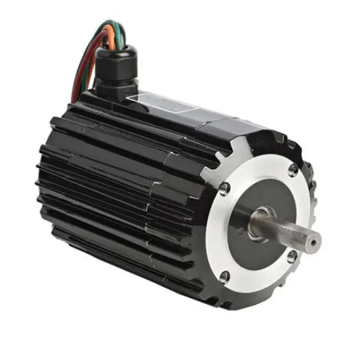
How is the efficiency of a DC motor determined, and what factors can affect it?
In a DC (Direct Current) motor, efficiency refers to the ratio of the motor’s output power (mechanical power) to its input power (electrical power). It is a measure of how effectively the motor converts electrical energy into mechanical work. The efficiency of a DC motor can be determined by considering several factors that affect its performance. Here’s a detailed explanation of how the efficiency of a DC motor is determined and the factors that can influence it:
The efficiency of a DC motor is calculated using the following formula:
Efficiency = (Output Power / Input Power) × 100%
1. Output Power: The output power of a DC motor is the mechanical power produced at the motor’s shaft. It can be calculated using the formula:
Output Power = Torque × Angular Speed
The torque is the rotational force exerted by the motor, and the angular speed is the rate at which the motor rotates. The output power represents the useful work or mechanical energy delivered by the motor.
2. Input Power: The input power of a DC motor is the electrical power supplied to the motor. It can be calculated using the formula:
Input Power = Voltage × Current
The voltage is the electrical potential difference applied to the motor, and the current is the amount of electrical current flowing through the motor. The input power represents the electrical energy consumed by the motor.
Once the output power and input power are determined, the efficiency can be calculated using the formula mentioned earlier.
Several factors can influence the efficiency of a DC motor:
1. Copper Losses:
Copper losses occur due to the resistance of the copper windings in the motor. These losses result in the conversion of electrical energy into heat. Higher resistance or increased current flow leads to greater copper losses and reduces the efficiency of the motor. Using thicker wire for the windings and minimizing resistance can help reduce copper losses.
2. Iron Losses:
Iron losses occur due to magnetic hysteresis and eddy currents in the motor’s iron core. These losses result in the conversion of electrical energy into heat. Using high-quality laminated iron cores and minimizing magnetic flux variations can help reduce iron losses and improve efficiency.
3. Friction and Windage Losses:
Friction and windage losses occur due to mechanical friction between moving parts and air resistance. These losses result in the conversion of mechanical energy into heat. Proper lubrication, efficient bearing systems, and aerodynamically optimized designs can help minimize friction and windage losses.
4. Brush and Commutator Losses:
In brushed DC motors, brush and commutator losses occur due to the friction and electrical resistance at the brush-commutator interface. These losses result in the conversion of electrical energy into heat. Using high-quality brushes and commutators, reducing brush voltage drop, and minimizing the number of commutator segments can help reduce these losses.
5. Magnetic Field Design:
The design of the magnetic field in the motor significantly affects its efficiency. Optimizing the magnetic field for the specific application, such as selecting appropriate magnet materials or designing efficient electromagnets, can improve the motor’s efficiency.
6. Motor Load:
The load on the motor, including the torque and speed requirements, can impact its efficiency. Operating the motor close to its optimal load conditions or utilizing speed control techniques, such as pulse width modulation (PWM), can help improve efficiency by reducing unnecessary power consumption.
7. Motor Size and Construction:
The size and construction of the motor can influence its efficiency. Properly sizing the motor for the intended application and optimizing the design for reduced losses, improved cooling, and efficient heat dissipation can enhance overall efficiency.
It’s important to note that the efficiency of a DC motor is typically highest at or near its rated load conditions. Deviating significantly from the rated load can result in reduced efficiency.
In summary, the efficiency of a DC motor is determined by comparing the output power to the input power. Factors such as copper losses, iron losses, friction and windage losses, brush and commutator losses, magnetic field design, motor load, and motor size and construction can all influence the efficiency of a DC motor. By considering and optimizing these factors, the overall efficiency of the motor can be improved.
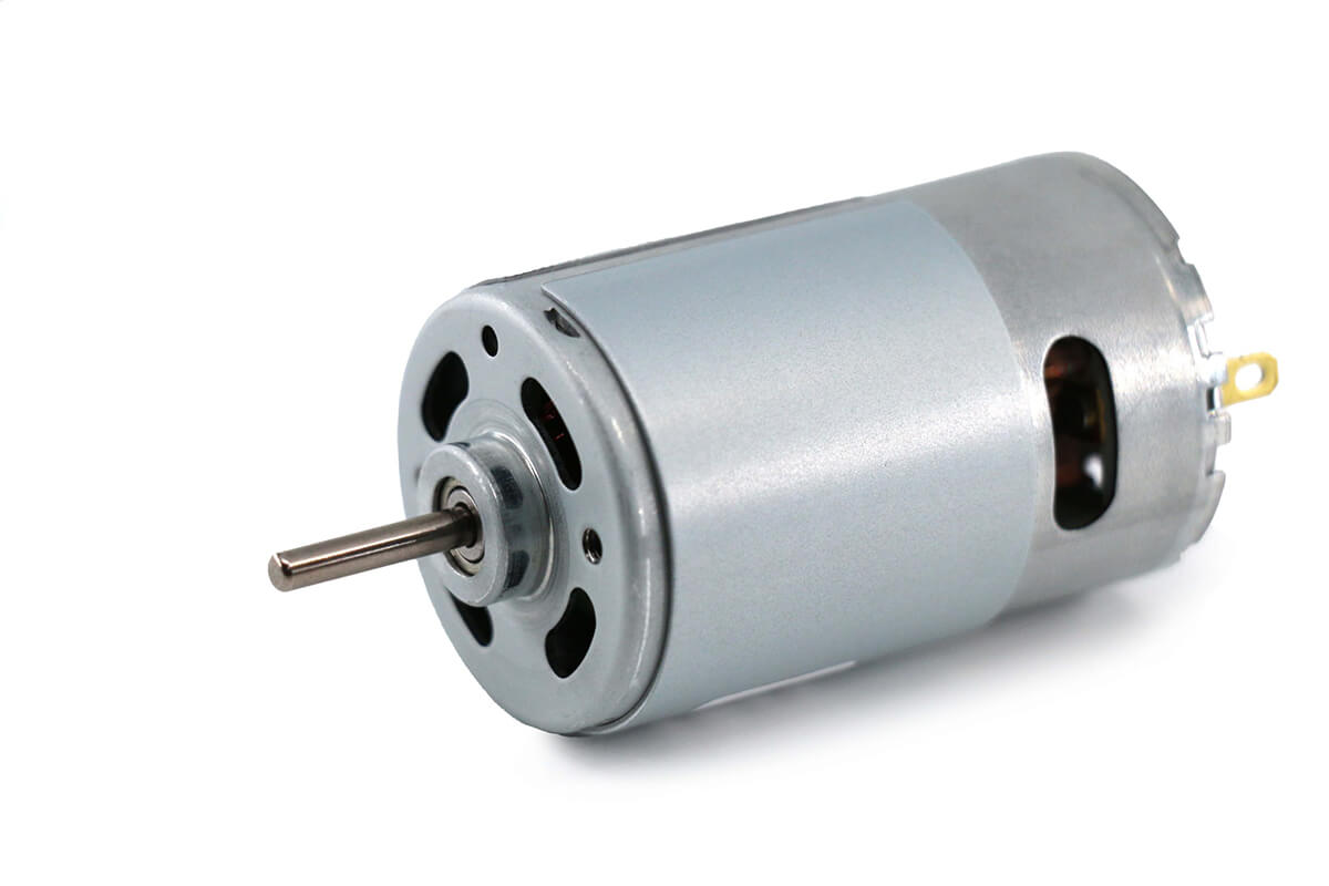
Are there safety considerations or maintenance practices associated with DC motors?
Yes, there are safety considerations and maintenance practices associated with DC (Direct Current) motors. DC motors, like any other electrical equipment, require proper handling, maintenance, and adherence to safety guidelines to ensure safe operation and longevity. Here’s a detailed explanation of the safety considerations and maintenance practices associated with DC motors:
Safety Considerations:
Electrical Hazards: DC motors operate with high voltages and currents, posing electrical hazards. It is essential to follow proper electrical safety practices, such as wearing appropriate personal protective equipment (PPE) and ensuring that electrical connections are secure and insulated. Proper grounding and isolation techniques should be employed to prevent electrical shocks and accidents.
Lockout/Tagout: DC motors, especially in industrial settings, may require maintenance or repair work. It is crucial to implement lockout/tagout procedures to isolate the motor from its power source before performing any maintenance or servicing activities. This ensures that the motor cannot be accidentally energized during work, preventing potential injuries or accidents.
Overheating and Ventilation: DC motors can generate heat during operation. Adequate ventilation and cooling measures should be implemented to prevent overheating, as excessive heat can lead to motor damage or fire hazards. Proper airflow and ventilation around the motor should be maintained, and any obstructions or debris should be cleared.
Mechanical Hazards: DC motors often have rotating parts and shafts. Safety guards or enclosures should be installed to prevent accidental contact with moving components, mitigating the risk of injuries. Operators and maintenance personnel should be trained to handle motors safely and avoid placing their hands or clothing near rotating parts while the motor is running.
Maintenance Practices:
Cleaning and Inspection: Regular cleaning and inspection of DC motors are essential for their proper functioning. Accumulated dirt, dust, or debris should be removed from the motor’s exterior and internal components. Visual inspections should be carried out to check for any signs of wear, damage, loose connections, or overheating. Bearings, if applicable, should be inspected and lubricated as per the manufacturer’s recommendations.
Brush Maintenance: DC motors that use brushes for commutation require regular inspection and maintenance of the brushes. The brushes should be checked for wear, proper alignment, and smooth operation. Worn-out brushes should be replaced to ensure efficient motor performance. Brush holders and springs should also be inspected and cleaned as necessary.
Electrical Connections: The electrical connections of DC motors should be periodically checked to ensure they are tight, secure, and free from corrosion. Loose or damaged connections can lead to voltage drops, overheating, and poor motor performance. Any issues with the connections should be addressed promptly to maintain safe and reliable operation.
Insulation Testing: Insulation resistance testing should be performed periodically to assess the condition of the motor’s insulation system. This helps identify any insulation breakdown or degradation, which can lead to electrical faults or motor failures. Insulation resistance testing should be conducted following appropriate safety procedures and using suitable testing equipment.
Alignment and Balance: Proper alignment and balance of DC motors are crucial for their smooth operation and longevity. Misalignment or imbalance can result in increased vibrations, excessive wear on bearings, and reduced motor efficiency. Regular checks and adjustments should be made to ensure the motor is correctly aligned and balanced as per the manufacturer’s specifications.
Manufacturer’s Recommendations: It is important to refer to the manufacturer’s guidelines and recommendations for specific maintenance practices and intervals. Each DC motor model may have unique requirements, and following the manufacturer’s instructions ensures that maintenance is carried out correctly and in accordance with the motor’s design and specifications.
By adhering to safety considerations and implementing proper maintenance practices, DC motors can operate safely, reliably, and efficiently throughout their service life.


editor by CX 2024-03-30